There are two reasons we need to callibrate the Accutron test set for Silver Oxide batteries: Firstly, the working range of silver cells is slightly different to that of Mercury cells, and we would like to ensure that we get maximun useable life from the Silver cells. To get maximum life from the cell, we have to adjust the index mechanism of the watch such that it will index correctly at the highest voltage of a cell when it is new, and such that the watch will run until the voltage has dropped to a level at which the battery is considered exhausted. For Mercury batteries, the working range is 1.37V down to 1.05V, (or 0.32v range), while the silver oxide batteries, the range is from 1.63V down to 1.35V, (or 0.27V range). Secondly, we want to make sure the test set will be adjusted in such a way that it will handle the normal range of currents drawn by movements, which may vary by up to about 25% even among those of the same type. Note: Your recalibrated meter is good for modified and non-modified coils.
Tools/Materials RequiredRemove the 4 screws on the meter top plate and lift the meter out of its case. Before we start, it's worth having a visual examination of the meter, and make sure all the solder joints look sound (especially the rotary switch terminals), and that the meter terminals are tight.
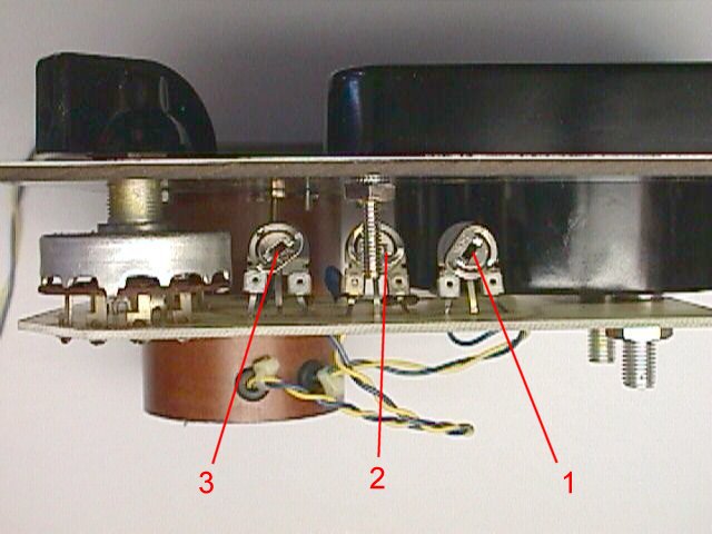
Step 2Connect the 218 movement to the meter, and set the meter to the Low Amplitude setting. With the meter horizontal, note the meter reading. If the movement is drawing around 8uA, adjust Pot #2 until you get a voltage reading of 1.41v at the movement cell terminals. If the movement is drawing around 10uA, then set the voltage reading to be around 1.39v.
Step 3Disconnect the 218 movement and connect the 214 movement, again with the switch at the Low Amplitude setting. With the meter horizontal again, note the meter reading. If the movement is drawing around 6uA, adjust Pot #1 until you get a voltage reading of 1.37v at the movement cell terminals. If the movement is drawing around 8uA, then set the voltage reading to be around 1.35v. The chances are that the pot will be rotated as far clockwise as it will go (though note, there is a position at the end of its travel where it disconnects and then starts at the highest voltage reading again). Unfortunately, the design of the meter does not allow us to get the low amplitude voltage quite as high as we would prefer, but that's life!
Step 4Remove the 214 movement and re-connect the 218. Check its readings as per Step 2. If they have moved a little, then repeat steps 2 and 3 again. They should not have changed by much, if at all. The circuit design of the meter is such that there is a little interaction between the two adjustments.
Step 5Disconnect any movement still connected, then place the switch in the "Check Power Cell" position. Measure the voltage of the power cell on the front of the meter. With the meter horizontal position, adjust the Pot #3 so that the meter reads the correct voltage.
Step 6Replace the meter back into its cover, install the 4 screws, and you're done!